 en
en English
 中文简体
中文简体 Español
 русский
 Français
 عربى
عربى Deutsch
 Português
 日本語
日本語 한국어
한국어 italiano
Shengya
Shengya
Shengya
Shengya
Shengya
Shengya
Shengya
Shengya
Shengya
What Is a Linear Magnetic Deburring Polisher and What Makes It Different?
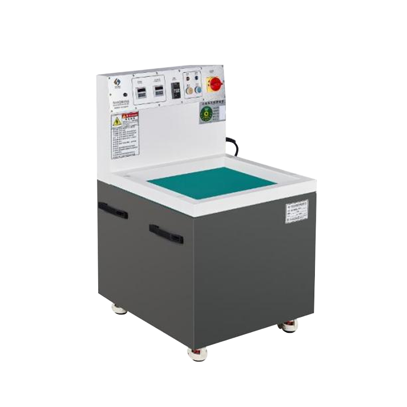
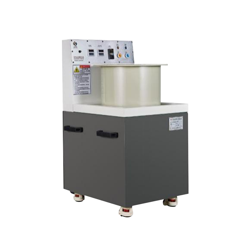
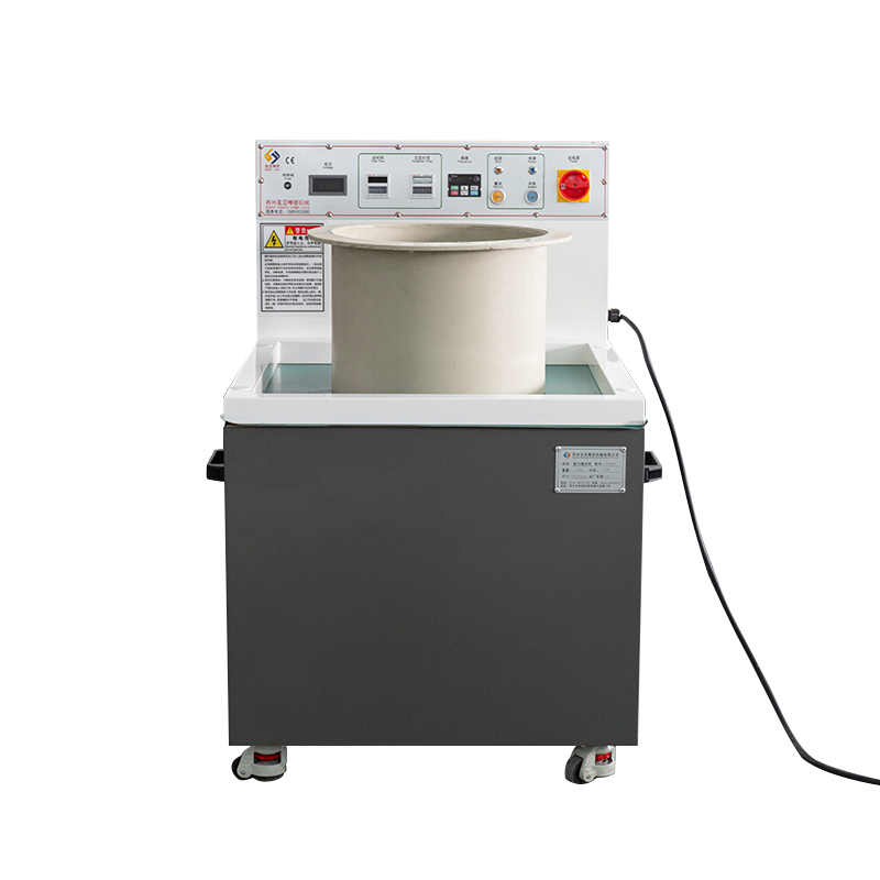
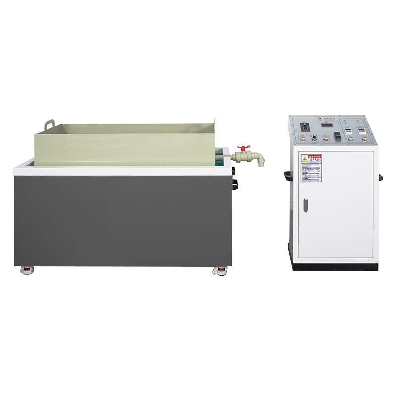
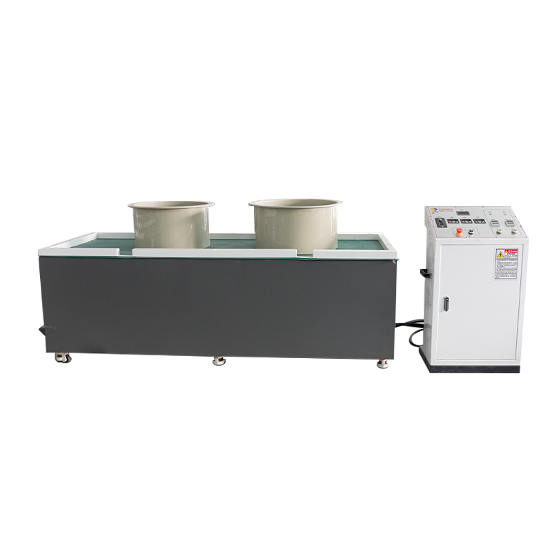
A linear magnetic deburring polisher is a finishing machine that uses a rotating magnetic field to drive thousands of small stainless steel pins across the surfaces of metal parts simultaneously, removing burrs, smoothing sharp edges, cleaning weld spatter, and producing a bright polished finish — all in a single automated process. Unlike vibratory tumblers that rely on abrasive media and gravity, or belt sanders that contact only one surface at a time, a linear magnetic polisher reaches every surface, internal thread, hole, slot, and recessed feature of a part in one pass with no manual repositioning required.
The "linear" in the name refers to how the magnetic field moves. Beneath the stainless steel work bowl, a set of permanent magnets is mounted on a rotating disc driven by an electric motor. As the disc spins, the magnetic field sweeps in a consistent linear pattern across the bowl floor, driving the steel pins in a controlled, directional motion rather than a random tumbling action. This linear motion is what gives the machine its edge over conventional rotary magnetic tumblers — the pins move with greater uniformity across the full bowl surface, producing more consistent results across every part in the batch, whether the batch contains 5 parts or 500.
The process is wet: parts, pins, and a water-based compound solution are loaded together into the bowl. The compound — typically a mild alkaline cleaning agent or a purpose-formulated polishing additive — lubricates the pin-to-part contact, carries away the swarf and burr debris generated during the process, and contributes to the final surface brightness. At the end of the cycle, parts are separated from the pins using a magnetic separator screen, rinsed, and either moved to the next process step or dried and packaged. The entire cycle for a typical small metal component takes between 5 and 30 minutes depending on the material, the severity of burrs, and the finish target.
How the Magnetic Deburring Process Works: The Physics Behind the Pins
To use a linear magnetic polishing machine effectively, it helps to understand what the pins are actually doing at a microscopic level and why the magnetic drive system produces such consistent results.
The Role of the Rotating Magnetic Field
The motor beneath the bowl drives a disc carrying an array of alternating-polarity permanent magnets. As the disc rotates, the magnetic field experienced at any point on the bowl floor alternates in direction at the frequency determined by the motor speed — typically adjustable between 800 and 3,000 RPM on most machines. The stainless steel pins sitting in the bowl are ferromagnetic and respond to these field changes by aligning with the instantaneous field direction and then flipping to align with the next. This continuous realignment drives the pins in a sweeping, directional motion across the bowl. The speed and intensity of this motion is controlled by adjusting the motor RPM, giving the operator direct control over the aggressiveness of the finishing action.
What the Pins Do to the Part Surface
Each pin is a precision-manufactured stainless steel cylinder or needle, typically 0.3mm to 1.0mm in diameter and 3mm to 30mm in length. At the speeds generated by the magnetic field, these pins strike the part surface thousands of times per second across every exposed face. On burrs — which are thin, unsupported projections of material left by cutting, punching, or drilling — this repeated micro-impact fatigue-fractures the burr at its base, removing it cleanly. On sharp machined edges, the same action rounds the edge to a consistent, controlled radius. On the broader surface, the pin impacts create a compressive work-hardening effect that refines the surface texture and produces the characteristic bright, satin polish associated with the process.
The Role of the Compound Solution
The water-based compound in the bowl performs several functions simultaneously. It lubricates pin-to-part contact, which prevents the pins from scratching rather than polishing at high speeds. It acts as a coolant, preventing heat buildup in small parts that could cause discoloration or dimensional change in tight-tolerance components. It carries deburring debris and fine swarf away from the work surface, preventing already-removed material from being re-embedded into the part. And it contributes directly to the surface finish — alkaline compounds promote brightness on steel and titanium, while purpose-formulated polishing compounds for non-ferrous metals like aluminum, brass, and copper optimize the finish for those specific materials.
What Materials and Parts Can a Linear Magnetic Polisher Handle?
One of the most common questions about magnetic deburring equipment is whether it will work on a specific material or part geometry. The honest answer is that the process handles a very wide range of materials and geometries — but with some important limitations that determine whether it's the right choice for your application.
Compatible Materials
Linear magnetic deburring polishers work on virtually all metals, including:
- Stainless steel — The most common application. The process produces a bright, consistent finish on 303, 304, 316, and other common grades, removes machining burrs cleanly, and polishes internal threads and bores that would be inaccessible by any other practical means.
- Carbon steel and tool steel — Deburrs effectively. Parts should be rinsed and dried promptly after processing to prevent flash rust, particularly with alkaline compounds that leave the surface chemically active.
- Titanium — The linear magnetic process handles titanium well, which is valuable because titanium is notoriously difficult to deburr by other methods due to its tendency to work-harden and its poor machinability. The low-force pin impact action avoids the heat generation that can cause surface discoloration in titanium.
- Aluminum and aluminum alloys — Processes cleanly with appropriate compound selection. Aluminum is soft enough that aggressive settings or large pins can leave micro-scratches, so smaller pin diameters (0.3mm to 0.5mm) and lower motor speeds are recommended for finishing work on aluminum parts.
- Brass and copper — Excellent results, particularly for jewelry, hardware, and precision instrument components. These materials respond quickly and produce a bright, attractive finish with short cycle times.
- Zinc die-cast parts — Handles well at moderate speeds. These parts often have parting-line flash and gate marks that the linear magnetic process removes efficiently.
Part Geometries That Benefit Most
The linear magnetic finisher excels specifically where other deburring methods struggle: complex geometries with internal features. Threaded holes, cross-drilled passages, internal bores, blind holes, slots, laser-cut holes, and thin-walled components with interior passages all process effectively because the pins can penetrate into features that are inaccessible to abrasive belts, grinding wheels, or manual tools. This makes the process particularly valuable for CNC-machined components, medical device parts, hydraulic manifolds, aerospace brackets, and precision instrument housings where internal burrs are both difficult to remove and unacceptable in the finished part.
Parts and Materials Not Suitable for This Process
Not every part is a candidate for magnetic deburring. Very large parts — those that don't fit within the bowl dimensions — are obviously excluded. Parts with very tight dimensional tolerances that cannot accept any material removal require careful process validation before running in production. Delicate parts with very thin walls (under 0.3mm) or fragile features risk deformation under pin impact at higher speeds. Non-metallic parts, including plastics, ceramics, and composites, are generally not suitable because they don't interact with the magnetic pins in the same way, although some operators successfully process plastic-bodied parts with metal inserts by containing the part geometry carefully. Soft metals like pure lead or tin can deform rather than deburr under pin impact.
Linear Magnetic Polisher vs. Other Deburring Methods: A Direct Comparison
Understanding where the linear magnetic deburring machine sits relative to other finishing options helps you decide whether it's the right investment for your specific situation.
| Method | Best For | Limitations | Internal Features? | Typical Cycle Time |
| Linear magnetic polisher | Small-to-medium complex parts, threads, internal holes | Not suitable for very large parts; some fragile geometries | Yes — excellent | 5–30 minutes |
| Vibratory tumbler | High-volume small parts, edge rounding | Slow; media lodges in features; less effective on internal burrs | Limited | 1–8 hours |
| Manual deburring | One-off parts, large parts, specific features | Labor-intensive; inconsistent; slow for production | With correct tools only | Variable |
| Electrochemical deburring | Precision internal burrs, hydraulic manifolds | High equipment cost; workpiece-specific tooling required | Yes — excellent | 1–5 minutes per part |
| Thermal energy deburring | Complex internal burrs, batch processing | Very high capital cost; oxidation risk on some materials | Yes — excellent | Seconds per cycle |
| Abrasive belt / grinding | Flat surfaces, outside edges, weld seams | External surfaces only; skilled operator required | No | Variable |
The linear magnetic polisher wins on versatility for small-to-medium complex parts, particularly when internal feature access and consistent batch quality are priorities. Its main disadvantage relative to vibratory finishing is part size limitation, and relative to electrochemical or thermal deburring, it requires longer cycle times. For most small machining shops, prototyping operations, and medium-volume production environments, it represents the most practical combination of capability, cost, and operating simplicity.
Key Specifications to Understand When Buying a Linear Magnetic Deburring Machine
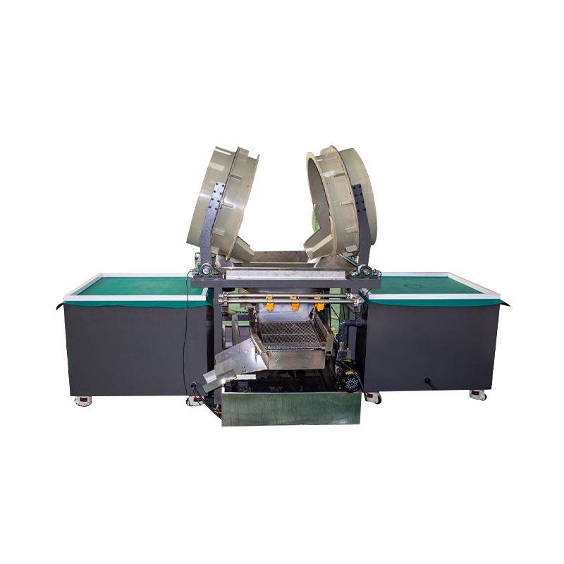
Shopping for a magnetic deburring polishing machine without understanding the key specifications leads to either buying a machine that can't handle your parts or overspending on capacity you don't need. Here are the specifications that matter most:
Bowl Size and Working Capacity
Bowl diameter is the primary sizing parameter and determines both the maximum part size and the batch capacity. Common bowl diameters range from 150mm for benchtop lab models up to 600mm or more for industrial production machines. As a rule, the largest part you'll process should fit comfortably within the bowl with at least 30–40mm clearance from the bowl wall on all sides, leaving room for the pins to circulate freely around it. Bowl depth is a secondary consideration — deeper bowls accommodate taller parts and provide more compound volume, which is important for parts with deep internal passages where the compound needs to penetrate and flush debris.
Motor Power and Speed Range
Motor power determines how forcefully the magnetic field drives the pins and therefore how aggressively the machine removes material. Higher power motors are needed for deburring heavier burrs on harder materials like tool steel or titanium. For polishing and light deburring on soft metals, lower power is adequate and produces less risk of over-processing delicate features. Variable speed control — adjustable across a range from approximately 800 to 3,000 RPM — is a standard feature on quality machines and is essential for matching the process intensity to the material and the target finish. Machines with only a fixed speed are significantly less flexible and should be avoided for general-purpose use.
Timer and Process Control
A programmable digital timer is a basic requirement on any production machine. This allows you to set exact cycle times for each part type, ensuring consistent results from batch to batch without requiring an operator to monitor the machine continuously. More advanced machines add features such as forward/reverse rotation cycling (which prevents parts from clustering and improves uniformity on complex geometries), multi-stage programmable cycles (for example, a roughing stage at high speed followed by a polishing stage at lower speed), and data logging for traceability in regulated manufacturing environments.
Pin Separation System
After processing, the pins and parts must be separated. This is done either manually — pouring the bowl contents over a mesh screen that holds the pins while parts and compound drain through — or automatically, using a built-in magnetic separator that draws the pins to one side while parts and compound drain away. Automatic pin separation significantly reduces process time and eliminates the risk of pins remaining lodged in part features, which is a genuine risk with manual separation on complex geometries. For any volume above hobby or prototype work, machines with integrated magnetic separation are strongly preferred.
Construction Quality and Bowl Material
The work bowl must be non-magnetic so it doesn't interfere with the magnetic field driving the pins. Bowls are typically made from austenitic stainless steel (304 or 316 grade), food-grade plastic, or non-magnetic ceramic-coated steel. Stainless steel bowls are the most durable and easiest to clean but the most expensive. Plastic bowls are lighter and lower cost but scratch over time and can harbor contamination in surface scratches when processing parts that must meet cleanliness specifications. The frame and base of the machine should be heavy enough to absorb vibration without walking across the workbench during operation — a machine that moves during the cycle is both a nuisance and a potential hazard.
Choosing the Right Pins for Your Application
The stainless steel pins used in a magnetic pin polisher are a consumable that must be matched to the application. Using the wrong pin diameter or length for the part being processed produces suboptimal results and can cause problems ranging from pins lodging in features to insufficient finishing action on heavy burrs.
Pin Diameter Selection
Pin diameter is the most important selection parameter. The diameter must be small enough to enter the smallest hole or feature on the part that needs deburring, but large enough to carry sufficient mass to generate effective deburring action. As a practical starting point: for M2 threaded holes and smaller bores (under 2mm), use 0.3mm diameter pins. For M3 to M6 threads and bores of 3–6mm, 0.5mm pins are standard. For M8 and above and larger features, 0.8mm or 1.0mm pins provide better deburring action on heavier burrs. Using pins that are too large for a feature simply means that feature doesn't get processed — the pins won't enter the hole and the burr remains.
Pin Length Selection
Pin length affects how the pins behave in the magnetic field and how they interact with part surfaces. Shorter pins (3–5mm) are stiffer under the magnetic drive and produce a more aggressive surface impact — better for deburring. Longer pins (10–30mm) flex more under the field and produce a more gentle, polishing-oriented action — better for final surface finishing. Many operators use a mixed pin charge — combining two or three different lengths — to get effective deburring action on edges and holes alongside polishing action on broader surfaces in a single cycle. This approach is particularly effective for parts that need both burr removal and a bright decorative finish from the same processing step.
Pin Maintenance and Replacement
Stainless steel pins wear down gradually through use — they shorten slightly with each cycle as the ends are worked against part surfaces. A pin charge that started at 5mm length may be 4mm after extensive use, which changes its behavior in the magnetic field. Monitor pin length periodically using a digital caliper and replace the pin charge when average length has reduced by more than 15–20% from new, or when surface finish results begin to deteriorate noticeably. Also inspect pins for bent or kinked specimens — these can scratch part surfaces rather than polishing them and should be removed by running the pin charge over a flat magnet and discarding any pins that don't lie straight.
Setting Up and Running Your First Batch: A Practical Process Guide
Understanding the theory is one thing — knowing exactly how to load and run a batch correctly from the start saves time and avoids the most common first-use mistakes.
Step 1: Prepare the Parts
Pre-clean parts before loading them into the magnetic deburring machine. Oil, cutting fluid, and heavy metal swarf from machining contaminate the compound quickly, reducing its effectiveness and shortening the service life of the pin charge. A simple solvent wipe or a quick dip in an ultrasonic cleaner removes the bulk of contamination before the magnetic process begins. Parts with large, heavy burrs — for example, thick flash on a stamped part — benefit from a pre-deburring step using a file or deburring tool to remove the bulk of the burr before magnetic processing refines the edge. The magnetic process excels at final deburring and polishing; trying to use it as a primary material removal process significantly extends cycle times.
Step 2: Load Pins and Compound
Fill the bowl to approximately one-third of its depth with pins. Add water to the level recommended by the machine manufacturer — typically covering the pins by 10–20mm. Add the compound at the dilution ratio specified by the compound supplier. For general steel deburring, a dilution of 1:20 (compound to water) is a common starting point, but follow the specific product instructions. Too little compound produces poor results; too much creates excessive foam that interferes with pin motion. If you're processing multiple batches, top up the compound concentration periodically as it depletes during use.
Step 3: Load the Parts
Place parts in the bowl on top of the pin bed. For small parts that might nest or stack against each other, distribute them evenly across the bowl surface and ensure no two parts are in contact — parts that touch each other can mask features from pin access and leave unpolished patches. For very small parts at risk of floating to the surface of the pin bed, load them submerged by gently pressing them into the pins initially. The ratio of parts volume to pins volume matters: a rough guide is that parts should make up no more than 30–40% of the total bowl loading to ensure adequate pin circulation around all surfaces.
Step 4: Set Speed and Time, Then Run
Start with a moderate speed — around 50–60% of the machine's maximum RPM — for the first trial batch. Set the timer to 10 minutes as an initial run, then stop the machine and inspect a sample part. If burrs remain, run an additional 5–10 minutes. If the surface is showing signs of over-processing (micro-scratches or etching on soft materials), reduce speed and shorten subsequent cycles. Document the speed and time that produces the target result for each part type and material, then use those parameters consistently for production runs. The time investment in process development upfront pays back in consistent, predictable results across every subsequent batch.
Common Applications and Industries That Use Linear Magnetic Finishers
Linear magnetic surface finishers appear across an impressively wide range of industries, united by the common need to finish small-to-medium metal parts to a consistent, high-quality standard without labor-intensive manual processing.
- CNC Machining Shops: Deburring turned and milled components, removing thread burrs from tapped holes, finishing medical and aerospace parts to tight cleanliness and surface finish specifications, and adding consistent edge breaks to precision components before assembly.
- Medical Device Manufacturing: Polishing surgical instruments, implant components, and device housings to the surface finish requirements needed for sterilization compatibility and biocompatibility. The process removes burrs from threaded implant features that would be inaccessible to manual tools without risk of contamination.
- Aerospace and Defense: Finishing precision fasteners, hydraulic fittings, avionics housings, and structural brackets where internal burrs in fuel or fluid passages present a contamination and reliability risk that is unacceptable in service.
- Jewelry and Watchmaking: Polishing rings, pendants, clasps, watch cases, and movement components to bright finish standards, including internal features of rings and bezels that are impossible to reach with conventional polishing tools.
- Automotive Components: Finishing fuel system components, hydraulic valve bodies, precision fasteners, and sensor housings where internal cleanliness and burr-free passages are critical to component function and service life.
- Electronics and Connectors: Deburring and polishing contact pins, connector housings, heat sink components, and structural hardware for electronic assemblies where sharp edges or burrs could damage wiring harnesses or circuit boards during assembly.
- Prototyping and R&D: Small magnetic polishers are increasingly common in engineering prototyping environments where CNC-machined development parts need to be quickly brought to a finished standard for functional testing, photography, or client presentation without the cost of outsourcing to a finishing subcontractor.
Troubleshooting: Why Your Magnetic Deburring Results Aren't What You Expected
Even with the right machine and the right pins, results sometimes fall short of expectations. Here are the most common problems and their causes:
Burrs Not Being Removed After a Full Cycle
This usually means the burrs are too heavy for the magnetic process to handle directly, the pin diameter is too large to access the feature, the motor speed is too low, or the cycle time is insufficient. Start by checking whether the pins are entering the relevant features — if they're too large to access a threaded hole, the burr inside that hole will never be touched. Increase speed in increments and extend cycle time. For very heavy burrs, pre-reduce them mechanically before magnetic finishing. Also check that the bowl isn't overloaded — too many parts prevent adequate pin circulation.
Parts Coming Out Scratched Rather Than Polished
Scratching indicates that the pin-to-surface contact is too aggressive or that the compound has become contaminated and is carrying abrasive particles. Check compound dilution — insufficient compound reduces lubrication and allows pins to scratch. Inspect the pin charge for bent or damaged pins and remove them. Reduce motor speed. If processing soft metals like aluminum or copper, switch to a smaller pin diameter and a compound formulated specifically for non-ferrous metals. Also check that parts are not directly contacting each other in the bowl, as metal-on-metal contact without pin cushioning between parts can cause scratching.
Pins Lodging Inside Part Features
This is a common problem with parts that have blind holes or slots where a pin can enter but then be trapped. Prevention is better than cure: select pin lengths that cannot fit fully inside the shortest blind feature on your parts — if your smallest blind hole is 8mm deep, use pins longer than 8mm so a lodged pin still protrudes and can be retrieved. After each cycle, inspect all internal features with a strong light source before marking parts as complete. For parts prone to pin retention, a secondary compressed air blow-out and a run over a strong handheld magnet help confirm all pins are recovered.
Inconsistent Results Across a Batch
If some parts in a batch come out well and others show incomplete deburring or uneven polish, the most common causes are uneven part distribution in the bowl, parts nesting against each other blocking pin access, or an overloaded bowl reducing pin circulation. Reduce batch size, distribute parts more carefully, and consider running a forward/reverse cycle if your machine supports it to improve uniformity. Also verify that the compound level is correct — a bowl that is too shallow doesn't cover all parts consistently during the cycle.
Maintenance and Care of Your Linear Magnetic Polisher
A well-maintained magnetic deburring machine runs reliably for many years with minimal downtime. The maintenance requirements are simple but must be performed consistently.
- Daily: Drain and rinse the bowl thoroughly after the last batch of the day. Don't leave compound and swarf sitting in the bowl overnight — the acidic or alkaline chemistry of processing compounds attacks bowl surfaces over time and can cause accelerated wear. Rinse the pin charge in clean water and allow to drain dry, or if the pins won't be used for several days, dry them completely to prevent surface rust on carbon steel components in the vicinity.
- Weekly: Inspect the bowl interior for scratches, pitting, or corrosion that could contaminate parts or harbor bacterial growth in food-contact or medical applications. Check the bowl mounting for tightness — vibration from the machine can loosen bowl fasteners over time. Wipe down the machine exterior and check that ventilation slots in the motor housing are clear of swarf and debris.
- Monthly: Check the motor bearing for unusual noise or vibration by running the machine empty and listening carefully. Early-stage bearing wear often manifests as a slight roughness in the sound that deteriorates progressively — catching it early allows a planned bearing replacement rather than an unexpected breakdown during a production run. Check all electrical connections, the speed control potentiometer, and the timer function.
- Pin Charge Management: Keep a log of processing hours or batch count for each pin charge. Establish a replacement interval based on observed pin wear for your typical application and replace the full pin charge at that interval rather than waiting for results to deteriorate. Mixing new and old pins is generally acceptable, but replacing the entire charge periodically ensures consistent process behavior.